

Injection molding operations run on precision and repeatability. Every cycle depends on consistent part removal, accurate placement, and minimal downtime between shots. When take-out robots fail to perform reliably, the consequences move quickly through the production floor — scrap rates climb, mold damage becomes a real risk, and cycle times fall out of specification. For manufacturers across North America operating high-volume thermoplastic production lines, the mechanical components inside take-out robots are not abstract engineering decisions. They are operational priorities.
Among those components, the linear actuator is one of the most consequential. It governs how the robot arm moves — how far, how fast, and how precisely — in three defined directions. Understanding how the three-axis movement system works, and how each actuator within it contributes to overall robot performance, helps engineering and operations teams make better decisions when specifying, maintaining, or replacing equipment. This is not theoretical. For plants running multi-cavity molds with tight tolerances, the linear actuator configuration directly determines whether the robot keeps pace with the press or becomes the bottleneck.
What a 3 Linear Actuator System Actually Does in a Take-Out Robot
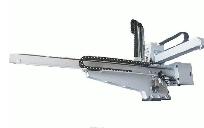
A take-out robot used in injection molding operates along three independent axes of movement: horizontal traverse across the press, vertical movement into and out of the mold area, and a kickback or secondary traverse that repositions the part after extraction. Each axis is driven by its own linear actuator — a mechanism that converts a power input, typically pneumatic or servo-electric, into controlled straight-line motion. The combination of these three actuators is what allows the robot to reach into an open mold, grip a finished part, retract cleanly, and deposit the part at a defined drop or conveyor position, all within a fraction of the molding cycle time.
For teams specifying or evaluating equipment, a well-structured 3 Linear Actuator guide offers a useful starting point for understanding how these axes interact, how they are rated for load and stroke, and what differentiates pneumatic from servo-driven configurations in real production environments.
The three-actuator architecture is not arbitrary. It reflects the physical geometry of a horizontal injection molding machine and the need for the robot to operate within the mold open time without slowing the press cycle. Each actuator must complete its motion accurately and return to a ready position before the next shot. Any delay or inconsistency in one axis compounds across the cycle.
The Role of Each Axis in Cycle Performance
The horizontal traverse actuator covers the longest distance in a typical cycle. It moves the robot arm from a home or standby position into the space above the mold, then returns it after extraction. Because this axis travels the greatest distance, it has the most significant influence on total cycle time. Robots with faster horizontal actuators can enter and exit the mold area more quickly, which allows the press to close sooner and maintain a tighter overall cycle.
The vertical actuator controls the drop into the mold cavity. This motion must be precise — descending far enough to position the end-of-arm tooling correctly relative to the part or sprue, but not so far that it contacts the mold surface. In multi-cavity applications or where parts have irregular geometry, vertical positioning accuracy directly affects grip consistency and part quality at the point of removal.
The kickback actuator, sometimes called the secondary horizontal or traverse axis, moves the part clear of the mold area after the vertical actuator retracts. In many installations, this axis also positions the part over a conveyor, chute, or secondary operation station. Its accuracy determines where parts land and how consistently downstream handling can occur.
Pneumatic vs. Servo-Electric Actuators in Injection Molding Applications
The choice between pneumatic and servo-electric linear actuators is one of the most significant decisions in configuring a take-out robot. Both technologies are capable of driving reliable three-axis motion, but they behave differently under production conditions and carry different implications for setup, maintenance, and process control.
Pneumatic actuators use compressed air to drive motion and have been the standard in injection molding take-out robots for decades. They are mechanically simple, cost-effective to maintain, and capable of high-speed operation. In applications where speed is the primary requirement and positioning follows fixed end-stops rather than programmable coordinates, pneumatic actuators perform well and are easy to service with standard tooling and parts.
Where Servo-Electric Actuators Provide a Measurable Advantage
Servo-electric actuators use a motor, drive, and feedback system to control both position and velocity with precision across the full range of travel. Unlike pneumatic systems, which typically operate between fixed endpoints, servo actuators can stop at any point along their stroke and adjust their speed profile based on where they are in the motion sequence. This flexibility matters when part geometry varies, when mold configurations change between runs, or when the robot must coordinate with auxiliary equipment at precise timing intervals.
For manufacturers running frequent mold changes or producing a wide range of part sizes on the same press, servo-driven three-axis systems reduce the time required to reprogram and validate robot positions. Instead of mechanically adjusting air cushions or repositioning hard stops, operators input new coordinates through the robot controller. This shortens changeover time and reduces the risk of setup errors that cause part damage or press interference.
Servo actuators also provide real-time feedback on position and load, which makes it possible to detect when a robot is operating outside normal parameters. If resistance on the vertical axis increases — which can indicate tooling wear, end-of-arm tooling contact, or a part that did not eject cleanly — the control system can flag the condition before it becomes a mold or equipment damage event.
Load Rating and Stroke Selection Relative to Part and Mold Requirements
Every linear actuator in a three-axis robot system carries a rated capacity for load and stroke. Load rating reflects how much weight the actuator can move reliably at speed, including the combined mass of the end-of-arm tooling and the part being extracted. Stroke defines the distance the actuator can travel in a single motion. Both parameters must be matched to the specific application — not the average case, but the most demanding combination the robot will regularly encounter.
Undersizing an actuator for load creates wear that accumulates gradually. The actuator may perform acceptably for months before the effects become visible in the form of inconsistent positioning, increased cycle time variation, or premature mechanical failure. This makes load matching particularly important at the specification stage, where the full range of tooling and part weights across all planned molds should be considered, not just the current application.
Stroke Requirements Across Different Press and Mold Configurations
Stroke requirements vary significantly depending on the size of the injection molding machine, the distance between tie bars, and the depth of the mold. A robot configured for a smaller press may have adequate stroke for current applications but become limiting if the plant upgrades to a larger press or begins running deeper molds. When specifying a three-axis robot system, building in some margin on stroke — particularly on the horizontal traverse and vertical axes — reduces the likelihood of needing to replace the robot as production requirements evolve.
Mold height and the clearance required for safe entry are closely related to vertical stroke. In applications where the mold has tall cores or where the part must be extracted at an angle to clear geometry, the vertical actuator must provide enough travel to position the gripper correctly without rushing the descent. Rushed vertical motion, driven by an undersized stroke that forces the actuator to operate near its limit, increases the probability of tooling contact with the mold and shortens the service life of both the actuator and the tooling.
Maintenance Patterns That Affect Long-Term Actuator Reliability
Linear actuators in high-cycle injection molding environments accumulate significant mechanical wear over time. The rate at which wear develops depends on how well the actuators are maintained, how consistently they are operated within rated parameters, and how quickly early warning signs are addressed. Maintenance programs that treat actuators as passive components — only replacing them after failure — consistently result in higher total costs and more unplanned downtime than programs built around condition monitoring and scheduled servicing.
According to general mechanical reliability principles recognized by organizations such as the International Organization for Standardization, preventive maintenance intervals should be established based on operating hours and usage conditions rather than calendar time alone. For robots running multiple shifts in high-volume production, this means tracking cycle counts and scheduling inspections at defined intervals rather than waiting for performance degradation to become apparent.
Early Indicators of Actuator Wear in Three-Axis Systems
In a three-actuator robot, wear rarely presents uniformly across all axes. The horizontal traverse actuator typically sees the highest cycle count and may show wear first. Signs that warrant closer inspection include increased positional variance over multiple cycles, unusual sound during traverse, or small inconsistencies in where the robot arm arrives at the end of a motion. These indicators, when caught early, allow maintenance teams to schedule servicing without disrupting production. When ignored, they tend to compound — a worn horizontal actuator affects the timing of the vertical axis, which in turn affects part placement accuracy on the kickback axis.
Lubrication intervals matter considerably in pneumatic actuator systems, where seal condition and bore cleanliness directly affect how consistently the actuator reaches its end position. Servo-electric actuators require attention to coupling integrity, motor feedback connections, and the mechanical condition of the drive components. Neither system is maintenance-free, and the assumption that actuators will continue to perform without regular attention is one of the more common sources of avoidable downtime on injection molding lines.
Conclusion
The three-axis linear actuator system in a take-out robot is not a background component. It is the mechanical core of how the robot performs, and its condition directly shapes cycle time, part quality, and the long-term reliability of the production line. Understanding how each axis functions, how to match actuator specifications to real application demands, and how to sustain performance through structured maintenance gives engineering and operations teams a clearer basis for both equipment selection and daily management decisions.
For North American manufacturers operating injection molding lines under competitive production pressure, these are not abstract technical considerations. They are practical decisions that affect output consistency, tooling life, and the confidence with which production teams can commit to delivery schedules. Getting the actuator configuration right at the start — and maintaining it properly through the robot’s service life — is one of the more reliable ways to protect cycle performance and reduce the costs associated with unplanned downtime.
