

Steam turbines operate under extreme conditions, and the reliability of condition monitoring systems directly determines whether a facility runs safely or faces catastrophic failure. The Bently Nevada 3300 XL proximity sensor system has become a cornerstone of turbine health monitoring, providing real-time shaft displacement data that keeps critical machinery running within safe parameters.
Yet even the most sophisticated sensor system delivers poor results when installed incorrectly. Field technicians regularly encounter problems rooted in preventable installation mistakes — incorrect gap settings, improper cable routing, grounding errors, and inadequate calibration. These errors don’t just degrade measurement accuracy; they can trigger false alarms, mask genuine faults, or cause complete monitoring system failures at the worst possible moment.

This guide is designed specifically for field technicians responsible for installing and maintaining 3300 XL proximity sensors in steam turbine applications. By walking through a structured installation process, identifying the most common errors, and providing clear troubleshooting procedures, this article equips you with the practical knowledge needed to ensure every installation performs reliably from day one. Following these practices protects both your equipment and your team.
Understanding 3300 XL Proximity Sensors and Steam Turbine Monitoring
The Bently Nevada 3300 XL proximity sensor system uses eddy-current technology to measure radial shaft displacement without physical contact. As the shaft rotates, the probe generates a magnetic field that interacts with the target material, producing a voltage output proportional to the gap distance. This continuous, non-intrusive measurement gives operators real-time insight into shaft position, vibration amplitude, and bearing behavior — data that forms the backbone of any effective steam turbine condition monitoring program.
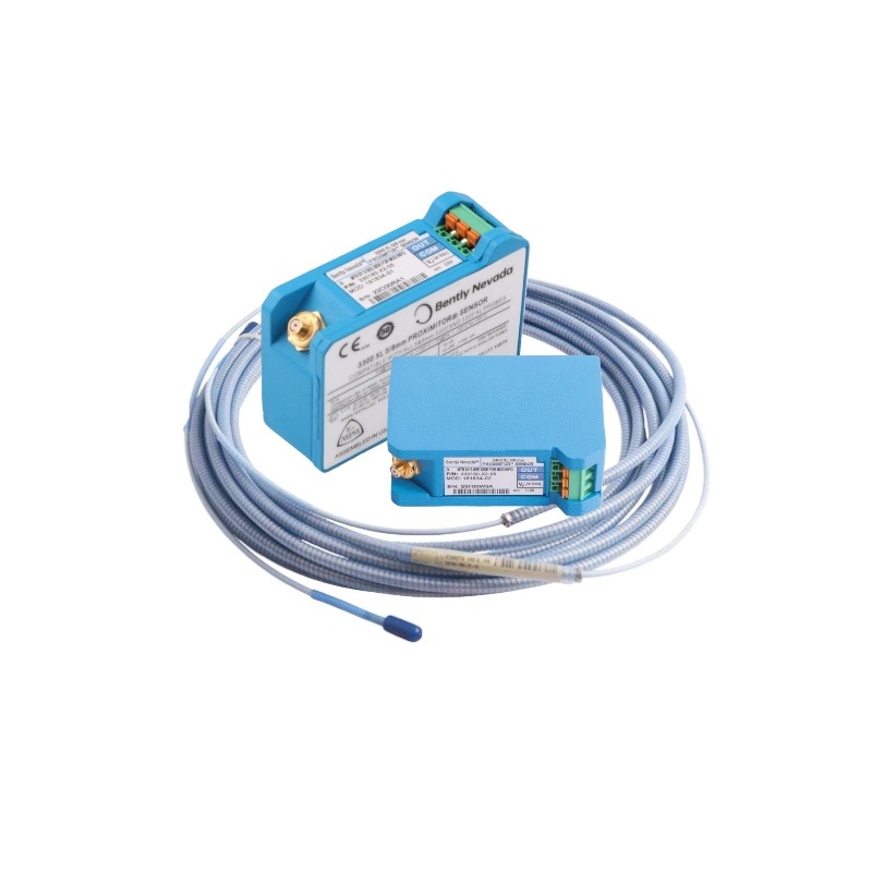
A complete 3300 XL system consists of several interdependent components: the proximity probe itself, an extension cable, and a Proximitor sensor that converts the probe signal into a usable voltage output. Each component must be properly matched and installed for the system to deliver accurate readings. Mixing incompatible cable lengths or using non-paired probes and Proximitors introduces measurement errors that can be difficult to trace after commissioning.
Accurate sensor data directly determines how well operators can detect developing faults such as oil whirl, rotor imbalance, or bearing degradation. When installation errors compromise signal integrity, the monitoring system may generate false trip signals during normal operation or, more dangerously, fail to alarm during an actual fault condition. Either outcome carries serious consequences — unplanned shutdowns, equipment damage, or personnel safety risks. Understanding how the system works at a fundamental level is the first step toward avoiding these outcomes.
Step-by-Step Installation Guide for 3300 XL Proximity Sensors
Pre-Installation Preparation and Safety Measures
Before touching any hardware, confirm the turbine is fully shut down and locked out according to your facility’s energy isolation procedures. Gather the required tools: a calibrated gap-setting tool or feeler gauge, digital multimeter, torque wrench, and the manufacturer’s installation drawings specific to your probe model. Verify that all 3300 XL components — probe, extension cable, and Proximitor sensor — are from a matched set with compatible cable lengths, typically 5 or 9 meters. Inspect each component for shipping damage, paying close attention to connector threads and cable jacketing. Check the mounting boss location against the turbine OEM specifications to confirm proper radial positioning before proceeding.
Mounting and Wiring Procedures
Thread the proximity probe into the mounting boss by hand first, then advance it until the probe tip is approximately 2.54 mm (100 mils) from the shaft surface — the nominal gap for most 3300 XL configurations. Use the locking nut to secure the probe at this position without disturbing the gap. Route the extension cable away from high-voltage wiring and heat sources, using dedicated conduit or cable trays where possible. Secure the cable at regular intervals to prevent vibration-induced fatigue at connector joints. Connect the extension cable to the Proximitor sensor, ensuring connectors are fully seated and hand-tightened. Mount the Proximitor in a location that stays within its rated temperature range and is accessible for future maintenance. Sourcing quality mounting hardware and conduit fittings from reputable industrial suppliers such as Apter Power can help ensure the mechanical integrity of the installation over the long term.
Initial Calibration and Verification
With power applied to the Proximitor, measure the output voltage using a digital multimeter at the monitor terminals. For a standard 3300 XL system, a gap of 2.54 mm should produce an output near -10.6 Vdc. Adjust the probe gap incrementally — no more than quarter-turn increments — until the output falls within the acceptable range specified in the calibration documentation. Record the final gap measurement and corresponding voltage. Verify the reading remains stable over several minutes, confirming there is no signal drift. Document all findings on the installation record sheet before declaring the channel ready for service.
Common Installation Errors and How to Avoid Them
Even experienced technicians make installation mistakes that compromise 3300 XL system performance. Recognizing these errors before they become embedded in a commissioned system saves significant diagnostic time and prevents monitoring gaps during turbine operation.
Incorrect gap setting is the most frequent offender. Technicians sometimes set the probe gap by feel rather than measurement, resulting in outputs outside the linear range of the Proximitor. A gap that is too tight risks physical contact during shaft excursions; a gap that is too wide pushes the output toward the nonlinear region of the calibration curve. Always verify the gap with a calibrated feeler gauge and confirm the corresponding voltage output before locking the probe in place.
Poor cable routing creates problems that only appear after commissioning. Running extension cables parallel to power cables or across hot exhaust surfaces introduces electrical interference and thermal degradation. Route signal cables through dedicated conduit separated from power runs by at least 150 mm, and never allow cables to contact surfaces exceeding the rated jacket temperature. Unsupported cable spans also generate vibration-induced fatigue cracks at connector joints — secure cables every 300 to 600 mm along their entire run.
Grounding errors are particularly damaging to signal integrity. A Proximitor that shares a ground path with variable-frequency drives or other noise sources will inject interference directly into the monitoring channel. Each Proximitor should connect to a dedicated instrument ground point with a measured resistance below 1 ohm to earth. Confirm ground integrity with a multimeter before powering the system.
Finally, mismatched components — pairing a probe with an incompatible extension cable length or a non-corresponding Proximitor — shift the entire calibration curve. Always verify part numbers against the matched-set documentation supplied with the system before installation begins.
Troubleshooting Common Issues with 3300 XL Proximity Probes
Diagnosing Signal and Calibration Problems
When a 3300 XL channel produces erratic or out-of-range readings, start at the Proximitor output terminals with a digital multimeter. A voltage reading outside the expected linear range — typically -2 Vdc to -18 Vdc — points to either a gap error or a failed component. Disconnect the extension cable from the Proximitor and measure the open-circuit voltage; if it reads approximately -24 Vdc, the Proximitor is functioning and the fault lies in the probe or cable. Many facilities run condition monitoring software that logs voltage trends over time — review this data to distinguish a sudden shift, which suggests physical damage or connector failure, from gradual drift, which typically indicates thermal expansion issues or a loosening probe locknut. Recalibrate the channel by resetting the gap to the nominal value and confirming the output voltage matches the calibration curve before returning the channel to service.
Resolving Physical and Environmental Interferences
Physical and environmental factors account for a significant share of field failures. Excessive shaft runout or surface irregularities on the target area generate signal noise that mimics real vibration events — inspect the shaft surface for scratches, rust, or plating inconsistencies and polish or repair as needed before recalibrating. High ambient temperatures near exhaust casings can push the Proximitor beyond its rated operating range, causing output saturation; relocating the Proximitor to a cooler bracket position or adding a thermal shield resolves this without compromising cable length. Contamination from oil mist coating the probe tip changes the effective gap and degrades signal linearity — clean the probe face with an appropriate solvent during scheduled outages and inspect the tip for pitting or corrosion. Installing the probe in a sealed mounting boss with a purge connection prevents recurring contamination in high-mist environments.
Best Practices for Long-Term Condition Monitoring with 3300 XL Components
Sustaining accurate proximity sensor performance over years of turbine operation requires more than a correct initial installation — it demands a disciplined maintenance routine and a systems-level view of how each component contributes to overall monitoring reliability. Establish a scheduled inspection interval, typically aligned with planned outages, to check probe gap settings, verify output voltages against baseline calibration records, and inspect cable jacketing and connector integrity. Even minor gap drift caused by thermal cycling or vibration-induced probe movement can shift readings enough to compromise alarm thresholds.
Integrating 3300 XL sensors into a broader condition monitoring solution means ensuring the Proximitor outputs feed correctly into your data acquisition and alarm management systems. Periodically validate the full signal chain — from probe tip to monitor display — rather than assuming the sensor alone is the only potential failure point. Components such as the 330180-90-05 proximity probe are precision-matched items; when replacement becomes necessary, always substitute with an identical matched set and recalibrate the channel from scratch rather than relying on the previous gap setting.
Technician training is equally important to hardware maintenance. Field personnel who understand eddy-current measurement principles make better diagnostic decisions and catch developing problems earlier. Maintain up-to-date installation records for every channel, including as-found and as-left gap measurements, voltage readings, and any component replacements. These records become invaluable during root-cause analysis after an unexpected alarm. Combining rigorous maintenance schedules, proper component management, and ongoing technician development creates the foundation for condition monitoring systems that remain dependable throughout the turbine’s service life.
Building a Foundation for Reliable Turbine Monitoring
Installing 3300 XL proximity sensors correctly is not simply a procedural formality — it is a direct investment in steam turbine safety, reliability, and operational continuity. This guide has walked through the complete installation process, from pre-installation preparation and component verification to gap calibration and signal confirmation. It has identified the errors most likely to undermine system performance — incorrect gap settings, poor cable routing, grounding faults, and mismatched components — and provided concrete steps to prevent each one before it becomes a costly problem.
Effective troubleshooting depends on understanding how the system behaves under normal conditions, which makes proper initial installation and thorough documentation equally important. When technicians maintain accurate baseline records and follow disciplined inspection routines, developing faults become far easier to identify and address before they escalate.
The practices outlined here are not one-time tasks. They represent an ongoing commitment to measurement integrity that protects both equipment and personnel throughout the turbine’s service life. Take the time to verify every installation, question any reading that deviates from baseline, and invest in keeping your team’s knowledge current. Reliable condition monitoring starts with getting the fundamentals right — and that begins with every proximity sensor installation performed to the highest standard.